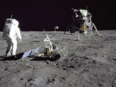
The engineering architecture of the Apollo Lunar Module (LM) was dictated not by aesthetic choices or structural paradigms, but by the immutable constraints of the Tsiolkovsky rocket equation. Operating within a strict weight envelope imposed by the Saturn V launch vehicle’s trans-lunar injection capacity, the vehicle’s designers at Grumman Aircraft Engineering Corporation had to minimize dry mass while maximizing delta-v ($\Delta v$) capability. The solution was an uncompromising, two-stage vehicle optimized exclusively for a vacuum environment, discarding every component not strictly required for the return journey.
To analyze the vehicle requires breaking it down into its core functional pillars: mass allocation efficiency, propulsive throttling dynamics, and the operational timeline of chemical deterioration. If you liked this article, you should read: this related article.
The Core Constraint: Mass Ratio and Multi-Stage Decoupling
The ultimate structural design of the Lunar Module was determined by structural efficiency. The vehicle was divided into two distinct components: the descent stage and the ascent stage. This configuration isolated the mass penalties of the landing gear, scientific payloads, and surface life-support expendables to the lunar surface, preventing them from penalizing the ascent trajectory.
[Apollo Lunar Module Total Mass: ~15,200 kg]
  ├── Descent Stage (~10,150 kg) -> Left on Moon
  │     ├── Propellant: ~8,165 kg (NTO/Aerozine-50)
  │     └── Dry Mass: ~1,985 kg (Engine, Legs, ALSEP Payload)
  └── Ascent Stage (~5,050 kg) -> Returns to Lunar Orbit
        ├── Propellant: ~2,358 kg (NTO/Aerozine-50)
        └── Dry Mass: ~2,692 kg (Crew Cabin, Avionics, RCS)
The mass distribution of a standard H-series Lunar Module demonstrates this optimization: For another perspective on this event, check out the recent coverage from Mashable.
- Total Launch Mass: Approximately 15,200 kg.
- Descent Stage Mass: Approximately 10,150 kg, of which roughly 8,165 kg was active propellant.
- Ascent Stage Mass: Approximately 5,050 kg, carrying 2,358 kg of propellant.
The vehicle's structural elements were stripped of aerodynamic fairings, windows were minimized in size and thickness, and the outer skin consisted of thin aluminum alloy wrapped in aluminized Mylar thermal blankets. This design achieved a dry mass fraction of less than 30% for the combined vehicle, optimizing the fuel budget for the critical maneuvers.
The separation mechanism relied on pyrotechnic nut cutters and an interstage umbilical guillotine. The ascent stage engine ignited while still physically mated to the descent stage—a process known as "fire-in-the-hole" staging. The descent stage served as a stable launch pad, absorbing the initial exhaust forces and saving the weight of a dedicated terrestrial launch pad structure.
Propulsive Dynamics and Throttling Mechanics
Landing a spacecraft in a vacuum requires a propulsion system capable of continuous deceleration against a changing vehicle mass. The descent propulsion system (DPS) used a hypergolic propellant combination: nitrogen tetroxide ($N_2O_4$) as the oxidizer and Aerozine-50 (a 50:50 blend of hydrazine and unsymmetrical dimethylhydrazine) as the fuel. This combination provided immediate ignition upon contact, eliminating the requirement for complex spark or torch igniters, which significantly mitigated risk.
The primary engineering hurdle of the lunar landing sequence was the thrust-to-weight ratio bottleneck. As the descent stage burned through its 8,165 kg of fuel, the vehicle's total mass decreased by more than half. To maintain a controlled descent rate without oscillating violently or overriding the guidance computer's autopilot limits, the DPS required a throttleable rocket engine—the first of its kind.
The engine was continuously throttleable between 10% and 100% of its rated 43.9 kN thrust capacity. A mechanical design constraint prevented efficient combustion between 65% and 92% thrust due to cavitation and flow instability risks, forcing the guidance computer to command either full thrust for the initial braking phase or low thrust (below 60%) for the final approach and hover phases.
The ascent propulsion system (APS) operated under an entirely different optimization matrix. While the descent engine required throttle capability and a gimbal mechanism for thrust vector control, the ascent engine required absolute mechanical simplicity to maximize reliability. The APS engine was fixed-thrust (15.57 kN), non-gimbaled, and relied purely on the Reaction Control System (RCS) thruster quads for attitude adjustments during the climb back to lunar orbit.
The Timeline Degradation Bottleneck
The decision to isolate the ascent and descent propulsion systems into two distinct physical loops was driven by material science limitations. Hypergolic propellants are highly corrosive. Once the isolation valves were explosively opened to pressurize the fuel lines with helium gas, a strict chemical degradation clock began ticking.
The internal valve seals and bladder materials inside the propellant tanks were rated for a maximum operational window:
- Descent System Limit: 3.5 days after initial helium pressurization. Beyond this window, acid exposure threatened to degrade fuel line integrity, risking regulator failure or spontaneous line bursts.
- Ascent System Limit: 24 hours from activation to engine cut-off.
A single-stage architecture would have required a single engine and plumbing network to handle both the landing, the surface stay, and the liftoff. This configuration would expose the primary valves to highly corrosive hypergolic vapors for up to five days, presenting an unacceptable risk profile. By separating the systems, the ascent stage remained completely sealed and isolated from corrosive vapor exposure until minutes before lunar liftoff, guaranteeing an uncompromised propulsion system for the return journey.
Guidance Integration and Human-in-the-Loop Override
The flight path from a 15-kilometer perilune down to the lunar surface was managed by the Apollo Guidance Computer (AGC) via a closed-loop system feeding off two primary sensors: the inertial measurement unit (IMU) and the landing radar.
The descent profile was executed in three distinct logical phases:
- Braking Phase: Characterized by maximum engine thrust (100%) with the vehicle oriented windows-down and parallel to the surface. This orientation allowed the landing radar to acquire altitude and velocity data early, overriding the purely mathematical integration of the IMU.
- Approach Phase (Pitch-over): At approximately 2.3 kilometers altitude, the computer pitched the vehicle upright, allowing the crew to visually inspect the landing site through the triangular, canted windows.
- Landing Phase: The final 200 meters allowed for a human-in-the-loop override. The commander could transition from full computer control to a semi-manual mode, redesignating the landing target via the computer joystick or taking direct control of the attitude thrusters while the computer maintained a fixed descent velocity.
The physical interface omitted traditional pilot seats to save weight. The crew stood inside the 6.7 cubic meter cabin, secured by a series of spring-loaded pulleys and cables. This design allowed the crew's eyes to be positioned close to the canted windows, maximizing downward visibility without requiring large, heavy glass panes.
Operational Imperatives for Future Surface architectures
The architecture of the Apollo Lunar Module demonstrates that minimizing total mission dry mass requires a strict alignment between staging boundaries and operational phases. For current and future exploration architectures, this logic dictates that single-stage reusable landers are structurally inefficient unless supported by local resource infrastructure.
The immediate tactical play for deep-space vehicle development requires utilizing multi-stage expendable or specialized methane-oxygen architecture. These configurations allow engineers to decouple landing systems from long-term habitat volumes, mitigating the risk of valve degradation and maximizing payload delivery per kilogram of initial low-Earth orbit mass.